New System Commissioning
Inspect an energized installation prior to turnover to identify thermal anomalies and establish initial system condition.
SOLAR PV THERMAL INSPECTIONS
ThermaVista provides aerial and ground-based infrared thermography for commercial and utility photovoltaic systems, helping owners, EPC contractors, commissioning teams, and O&M providers identify thermal anomalies quickly and document system condition with actionable evidence.
SEE WHAT NORMAL IMAGERY MISSES
Many photovoltaic defects are difficult or impossible to identify through conventional visual inspection alone. Under appropriate operating conditions, defective cells, electrical connections, bypass components, and other abnormalities can produce distinct thermal patterns.
Radiometric infrared imaging allows those temperature differences to be measured, mapped, and compared across large PV installations. Drone-based inspection makes that process practical even across hundreds or thousands of modules.
ThermaVista combines aerial imaging with targeted ground thermography to provide both broad system coverage and detailed inspection of electrical equipment.
WHEN TO USE THERMAL INSPECTION
The inspection strategy depends on where the PV system is in its lifecycle and what decision the inspection needs to support.
Inspect an energized installation prior to turnover to identify thermal anomalies and establish initial system condition.
Provide thermal evidence that can support project punch lists, quality assurance, corrective work, and final acceptance.
Inspect operating systems at regular intervals to identify new abnormalities before they develop into larger problems.
Use targeted thermal inspection to help localize suspected production, module, string, connector, or electrical issues.
WHAT THERMAL IMAGING CAN REVEAL
Infrared thermography identifies abnormal thermal behavior. The resulting patterns can help direct electrical testing, troubleshooting, maintenance, and corrective action.
| Thermal Observation | Possible Condition | Why It Matters | Typical Follow-Up |
|---|---|---|---|
| Individual hot cell | Cell damage, mismatch, cracking, localized shading, or other module abnormality | May affect module performance and could indicate a developing failure mechanism | Visual inspection, electrical testing, module evaluation |
| Substring heating | Bypass diode or substring-related condition | May indicate reduced module output or abnormal current flow | Electrical evaluation and module troubleshooting |
| Entire module warmer than adjacent modules | Open circuit, wiring issue, operating mismatch, or module-level electrical condition | May indicate loss of production or abnormal module operation | String-level electrical testing and inspection |
| Connector hotspot | Increased resistance, poor contact, contamination, improper assembly, or connection degradation | Resistive heating may increase over time and warrants investigation | Qualified electrical inspection and corrective evaluation |
| Junction-box heating | Internal connection, diode, or component abnormality | May indicate an electrical issue not visible externally | Targeted inspection and electrical diagnostics |
| String-level thermal difference | Current imbalance, open string, shading, mismatch, or electrical fault | May correspond with reduced production from an affected string | String current and voltage testing |
| Combiner or fuse heating | Resistive connection, fuse condition, imbalance, or conductor issue | Could affect reliability and electrical-system performance | Ground-based thermography and qualified electrical evaluation |
| Inverter termination hotspot | Abnormal resistance at a conductor or terminal connection | High-current connections can produce significant heating when resistance increases | Qualified electrician investigation and corrective action |
Thermal signatures identify abnormal temperature patterns and potential conditions; they do not necessarily establish root cause without appropriate follow-up evaluation.
STANDARDS-ALIGNED DATA COLLECTION
Thermal data is influenced by system load, sunlight, wind, weather, viewing geometry, equipment characteristics, and inspection technique. ThermaVista evaluates those conditions before relying on the resulting imagery.
Determine whether the PV system is operating under conditions appropriate for meaningful thermal evaluation.
Solar irradiance, cloud cover, wind, ambient temperature, and changing weather conditions are considered before and during data acquisition.
Infrared images retain temperature measurement information, allowing anomalies and temperature differences to be analyzed after acquisition.
Visible-light imagery helps identify the physical location of findings and distinguish thermal effects caused by shading, contamination, or physical conditions.
Findings are evaluated using temperature differences, pattern characteristics, surrounding equipment, and comparable assets.
Each relevant finding is associated with imagery, equipment identification, location, observations, and recommended follow-up.
INSPECTION CONDITIONS MATTER
PV thermal inspection depends upon meaningful electrical loading and sufficiently stable environmental conditions. These factors are evaluated and documented as part of the inspection.
WHY THE STANDARD MATTERS
IEC TS 62446-3 provides a framework for performing and documenting outdoor infrared thermographic inspections of operating PV systems. It addresses important elements of the inspection process, including:
The objective is not merely to capture attractive infrared photographs. It is to obtain thermographic data under controlled enough conditions that the results can support meaningful engineering, commissioning, and maintenance decisions.
AERIAL + GROUND THERMOGRAPHY
Large photovoltaic systems contain both expansive module fields and concentrated electrical equipment. The most useful inspection often combines both perspectives.
Drone thermography allows large areas of modules to be inspected efficiently while preserving location and visual context for detected anomalies.
Handheld thermography can evaluate inverters, combiners, disconnects, panelboards, switchgear, conductors, and electrical terminations under operating load.
Combining array-level and electrical-equipment findings provides a more complete representation of PV system condition than either technique alone.
INSPECTION WORKFLOW
Review drawings, array layout, equipment schedules, site access, and inspection objectives.
Acquire thermal and visible imagery under appropriate operating and environmental conditions.
Evaluate abnormal thermal patterns and compare similar equipment, modules, strings, or phases.
Document findings with equipment location, imagery, measurements, observations, and priorities.
Use findings to direct troubleshooting, corrective work, warranty review, or future condition monitoring.
ACTIONABLE REPORTING
Thermal images become valuable when the customer can determine exactly what equipment is involved, where it is located, why the finding matters, and what should happen next.
THE BUSINESS CASE
Developing electrical abnormalities frequently create heat before they create an obvious outage or visible failure.
Instead of searching an entire installation, maintenance personnel can begin with specific modules, strings, or components identified during inspection.
Module and string abnormalities may reduce production without causing an obvious system-wide failure.
Thermal inspection provides another layer of quality assurance after a new installation has been energized and placed under load.
Timestamped thermal and visible evidence can document the condition of equipment while installation and equipment warranties remain active.
Recurring inspections allow findings to be compared over time, helping distinguish isolated anomalies from developing trends.
INSPECTION OPTIONS
Aerial thermal inspection focused primarily on the PV array.
Combined PV and electrical thermography for new system commissioning.
Recurring thermal condition assessment for operating assets.
SOUTHERN CALIFORNIA
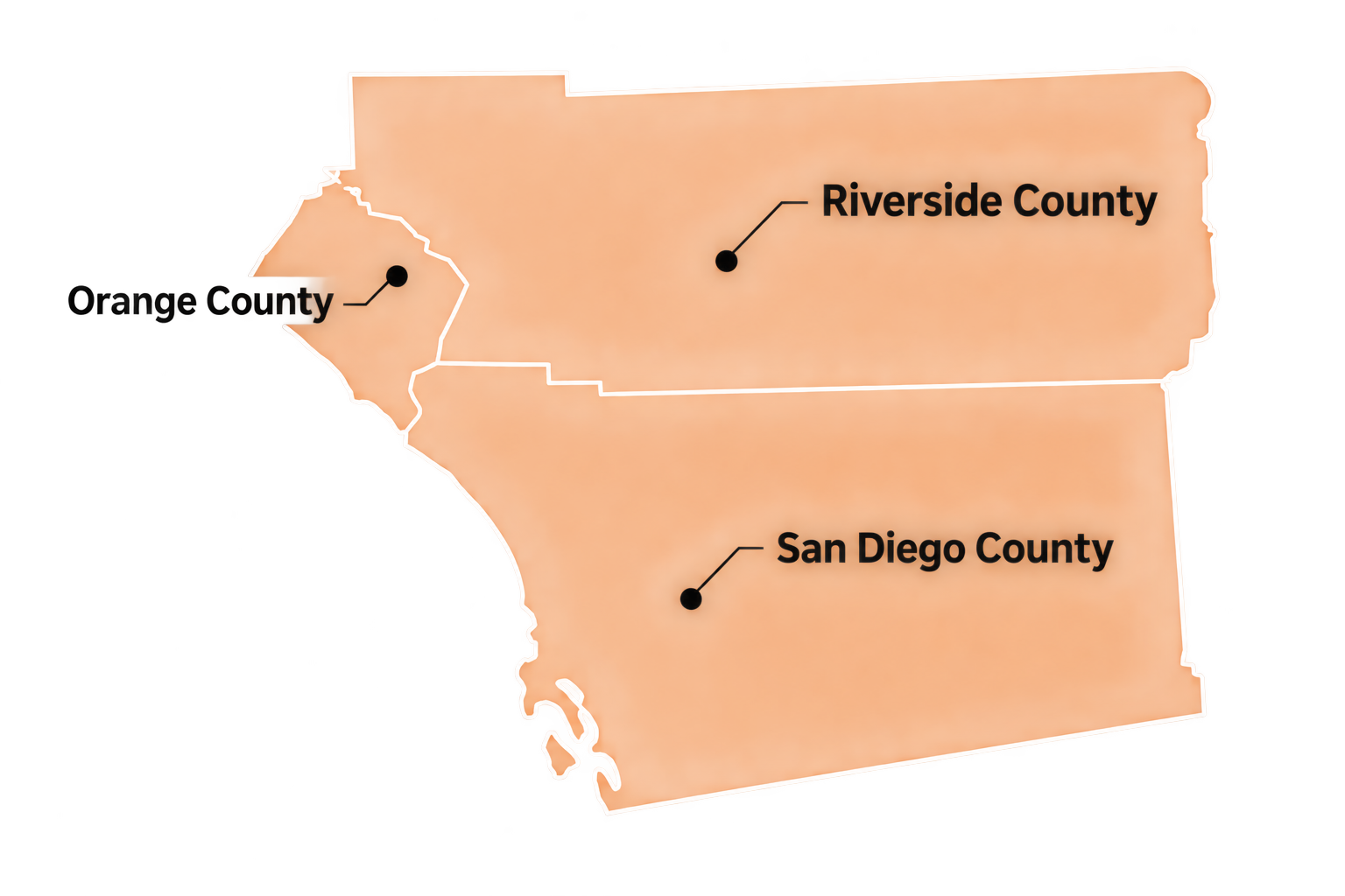
ThermaVista is based in North County and provides commercial and industrial solar inspection services throughout:
Typical projects include commercial rooftops, solar carports, municipal installations, schools, industrial facilities, commercial properties, ground-mounted PV, and larger distributed generation assets.
FREQUENTLY ASKED QUESTIONS
Thermal imaging can identify abnormal temperature patterns associated with certain module, cell, substring, connection, shading, and operating conditions. Thermography is generally used to locate and characterize anomalies; additional electrical or physical testing may be required to determine definitive root cause.
Commercial photovoltaic installations can contain thousands of modules spread across rooftops, carports, or ground-mounted arrays. A thermal drone can inspect large areas efficiently while collecting thermal and visible imagery with geographic context. Ground inspection remains valuable for electrical equipment and targeted follow-up.
Yes. Meaningful PV thermography generally requires the system to be operating under sufficient solar irradiance and electrical load. Environmental and system conditions are therefore an important part of inspection planning.
Variable clouds can rapidly alter module temperature and irradiance, reducing the reliability of thermal comparisons. Suitable inspection windows are selected based on environmental conditions and the objectives of the inspection.
Thermal inspection can provide useful commissioning information once the system is energized and operating. It may reveal abnormal conditions not apparent during conventional visual inspection and can establish a baseline for subsequent maintenance inspections.
Inspection frequency depends on asset criticality, operating environment, maintenance strategy, equipment history, owner requirements, and applicable maintenance programs. Many owners incorporate thermography into periodic condition-based maintenance rather than relying solely on one-time inspection.
Typical reports include inspection scope, methodology, environmental conditions, thermal and visible imagery, equipment identification, finding locations, temperature observations, anomaly descriptions, priorities, and recommended follow-up.
ThermaVista's primary role is inspection, thermographic analysis, documentation, and condition assessment. Findings can be provided to the owner's electrician, EPC contractor, O&M provider, equipment manufacturer, or other qualified service provider for corrective work.
REQUEST AN INSPECTION
Contact ThermaVista for commissioning, acceptance-support, or periodic thermal inspection of commercial photovoltaic systems throughout San Diego, Orange, and Riverside Counties.