Switchgear
Bus connections, breaker connections, cable terminations, protective devices, and accessible internal components.
ELECTRICAL THERMOGRAPHY
ThermaVista provides infrared thermographic inspection of commercial and industrial electrical systems to identify abnormal heating, compare similar components, document equipment condition, and support commissioning and preventive maintenance programs.
SEE CONDITIONS BEFORE THEY BECOME FAILURES
Electrical defects often develop gradually. A connection may loosen, corrode, deteriorate, or become overloaded while remaining visually unremarkable.
As resistance increases, heat can develop at the affected point. Infrared thermography allows these temperature differences to be identified while equipment is operating and carrying load.
By comparing similar components, phases, terminations, and operating conditions, thermography can help identify where additional investigation is warranted before a condition progresses into equipment damage or an outage.
ELECTRICAL EQUIPMENT
ThermaVista provides thermal inspection across common commercial, industrial, photovoltaic, and facility electrical systems.
Bus connections, breaker connections, cable terminations, protective devices, and accessible internal components.
Branch breakers, feeder breakers, phase conductors, neutral conductors, and termination points.
Switch contacts, line and load connections, fuses, conductors, and termination hardware.
Primary and secondary terminations, enclosure temperatures, bushings, and connection points.
AC and DC connections, breakers, cable terminations, internal connection points, and thermal distribution.
String connections, fuse holders, conductors, bus connections, and outgoing feeder terminations.
Accessible conductors, terminations, splices, taps, and high-current connection points.
Additional equipment may be evaluated where safe access, operating conditions, and inspection objectives permit.
WHAT THERMOGRAPHY CAN REVEAL
Thermography identifies unusual thermal behavior. Findings are interpreted in context and typically require follow-up by qualified electrical personnel to determine root cause.
| Thermal Observation | Possible Condition | Why It Matters | Typical Follow-Up |
|---|---|---|---|
| Single hot termination | Increased resistance, loose connection, corrosion, contamination, or contact degradation | Resistive heating can worsen under load and may damage conductors or equipment | Qualified electrical inspection and torque/connection evaluation |
| One phase hotter than adjacent phases | Load imbalance, connection issue, conductor problem, or abnormal resistance | Phase-to-phase comparison can reveal conditions that absolute temperature alone may not identify | Load measurement and electrical testing |
| Hot circuit breaker | High load, internal contact condition, poor terminal connection, or device deterioration | May indicate abnormal heating within or around the breaker | Load verification and breaker/termination evaluation |
| Fuse or fuse-holder heating | Poor contact, damaged fuse clip, overload, or fuse deterioration | Localized heating can affect reliability and component life | Electrical inspection and component evaluation |
| Hot bus connection | Increased resistance at bolted joint or connection interface | High-current bus connections can generate substantial heat when contact resistance increases | Qualified electrical inspection and corrective maintenance |
| Transformer termination hotspot | Loose or degraded primary/secondary connection | May indicate a developing high-resistance connection | Electrical investigation and testing |
| Abnormal conductor heating | Overload, undersized conductor, poor connection, harmonic loading, or imbalance | Elevated conductor temperature can accelerate insulation aging | Load analysis and conductor/circuit evaluation |
Thermography identifies temperature patterns and abnormal conditions. It does not, by itself, prove a specific electrical root cause.
WHY COMPARISON MATTERS
Electrical thermography is often based on comparison rather than looking at a single temperature reading in isolation.
Useful comparisons may include:
Load, emissivity, reflected temperature, equipment type, accessibility, viewing angle, and environmental conditions all affect interpretation.
INSPECTION METHODOLOGY
Reliable findings require suitable operating conditions, appropriate access, correct camera setup, and disciplined analysis.
Review equipment schedules, one-line diagrams, access requirements, inspection objectives, and operating constraints.
Thermography is most informative when electrical equipment is operating under meaningful and representative load.
Capture radiometric thermal imagery using appropriate viewing angles and measurement parameters.
Corresponding visible images help identify the exact component, equipment position, and physical condition.
Evaluate temperature differences, patterns, loading, similar components, and operating context.
Record equipment identification, location, thermal evidence, observations, priority, and recommended follow-up.
FINDING PRIORITIZATION
ThermaVista findings can be organized using a practical priority system that separates immediate concerns from conditions that should be monitored over time.
Priority categories shown above are a ThermaVista reporting framework and should not be represented as ANSI/NETA-defined classifications unless a specific standard or project specification requires them.
STANDARDS-ALIGNED INSPECTIONS
Different ANSI/NETA standards apply to different stages of an electrical system's lifecycle.
INSPECTION WORKFLOW
Review equipment lists, drawings, operating requirements, and access constraints.
Coordinate access, safety requirements, and operating conditions.
Capture thermal and visible imagery of accessible components.
Compare temperatures, similar components, phases, and loads.
Document location, equipment, findings, imagery, and priority.
Support maintenance teams with targeted information for further investigation.
INSPECTION REPORTING
A useful thermal report should make it possible for another technician to locate the exact equipment, understand the observed condition, and determine the appropriate next step.
THE BUSINESS VALUE
Identify abnormal conditions before they develop into equipment failures or service interruptions.
Direct maintenance teams toward specific components instead of treating every asset as equally urgent.
Identify abnormal heating in new installations once equipment is energized and carrying load.
Thermal patterns can quickly narrow the search area for electrical technicians.
Establish an initial thermal condition that can be compared against later inspections.
Periodic inspections help reveal whether a previously documented condition is stable or worsening.
SOUTHERN CALIFORNIA
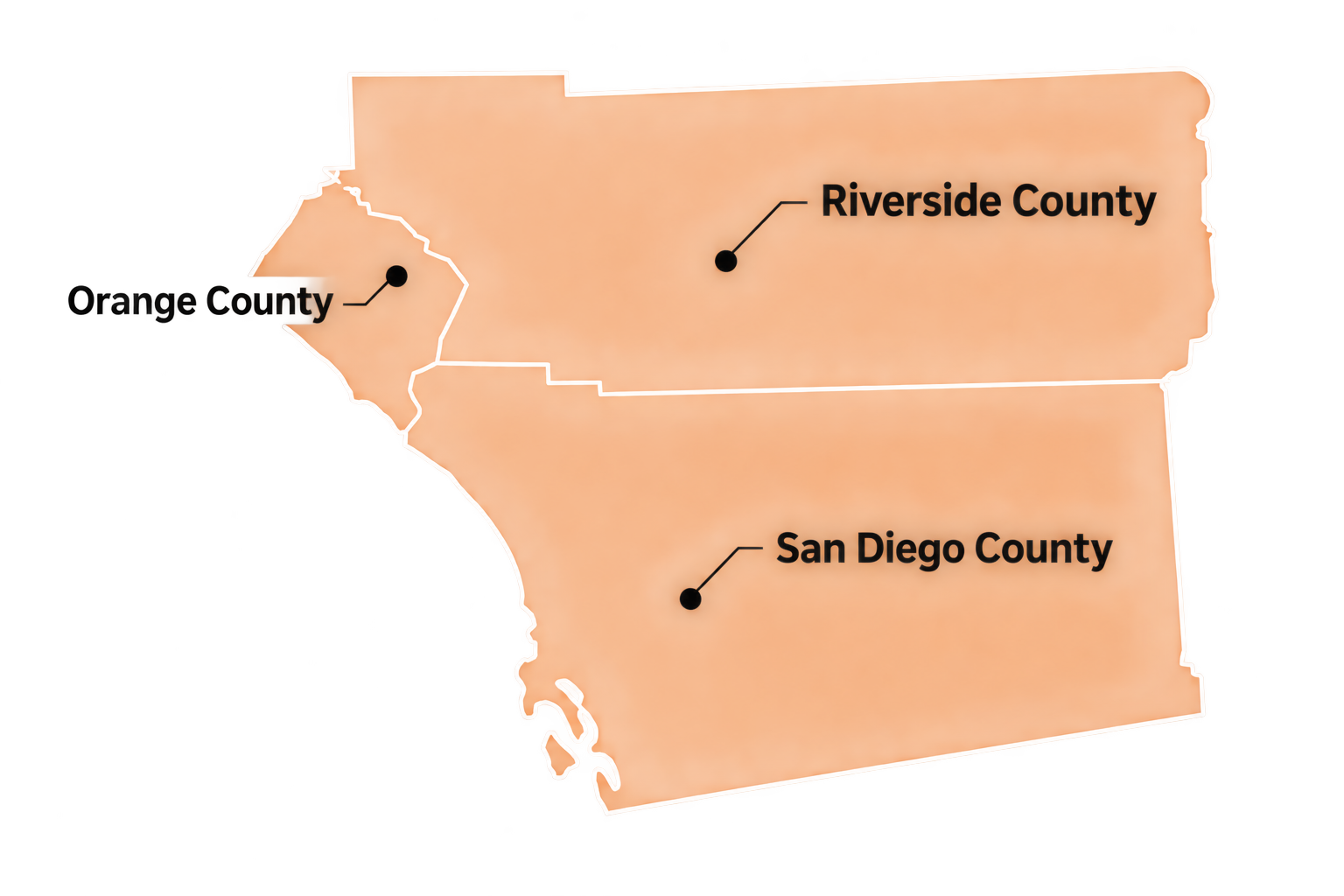
ThermaVista is based in North County and provides commercial electrical thermography throughout:
Typical clients include commercial facilities, industrial sites, solar installations, schools, municipalities, property owners, EPC contractors, O&M providers, and commissioning teams.
FREQUENTLY ASKED QUESTIONS
Generally, yes. Electrical thermography is most useful when equipment is operating under representative load because current flow is what produces the heating associated with many electrical abnormalities.
Not by itself. Thermography can identify a thermal pattern consistent with increased resistance or an abnormal connection, but mechanical or electrical evaluation is typically required to confirm the root cause.
Inspection depends on safe access, equipment design, electrical-safety requirements, site procedures, and the inspection scope. Open-panel or energized-equipment inspection must be coordinated with qualified personnel and the applicable electrical safety program.
Frequency depends on equipment criticality, loading, environment, maintenance history, owner requirements, and applicable maintenance programs. Higher-consequence equipment may justify more frequent condition monitoring.
No. New equipment can exhibit installation-related problems, poor connections, load imbalance, or component defects. Thermography can therefore be useful during commissioning as well as throughout the maintenance lifecycle.
Typical deliverables include thermal and visible imagery, equipment identification, temperatures, temperature differences, finding descriptions, priorities, and recommended follow-up.
REQUEST AN INSPECTION
Contact ThermaVista for commissioning, maintenance, or targeted electrical thermography throughout San Diego, Orange, and Riverside Counties.